Forward kinematics asks a simple question: if a robot's joints are at these angles, where is its tool? For a two-link arm on paper you can answer with trigonometry, but a six-axis industrial arm needs a system. The Denavit–Hartenberg (DH) convention is that system. It describes every joint with four numbers, turns each row into a 4×4 matrix, and multiplies them. This guide explains the four parameters, how to place the frames, and works through a full example with the numbers at every step.
The four parameters
Each joint i gets a coordinate frame, and four numbers describe how frame i sits relative to frame i−1. In the standard convention (Spong, Corke, most courses):
| Parameter | Measured | Meaning |
|---|---|---|
| θᵢ (joint angle) | about zᵢ₋₁, from xᵢ₋₁ to xᵢ | the rotation of a revolute joint |
| dᵢ (link offset) | along zᵢ₋₁, from xᵢ₋₁ to xᵢ | the slide of a prismatic joint, or a fixed offset |
| aᵢ (link length) | along xᵢ, from zᵢ₋₁ to zᵢ | the distance between the two joint axes |
| αᵢ (link twist) | about xᵢ, from zᵢ₋₁ to zᵢ | the angle between the two joint axes |
For a revolute joint θ is the variable and d, a, α are fixed by the robot's shape. For a prismatic joint d is the variable instead.
Placing the frames
The numbers only mean something once the frames are placed by the rules:
- zᵢ₋₁ lies along the axis of joint i: the line a revolute joint turns about, or a prismatic joint slides along.
- xᵢ lies along the common normal from zᵢ₋₁ to zᵢ, the shortest line between the two axes. If the axes intersect, xᵢ is perpendicular to both. If they are parallel, any common normal will do, and choosing it through the previous origin keeps d at 0.
- yᵢ completes a right-handed frame.
Then read the four parameters off the picture. Two shortcuts catch most cases: parallel joint axes mean α = 0, and perpendicular axes mean α = ±90°.
One matrix per row
Each row becomes a homogeneous transform, the product of a rotation and a translation along z, then a translation and a rotation along x:
Aᵢ = Rot_z(θᵢ) · Trans_z(dᵢ) · Trans_x(aᵢ) · Rot_x(αᵢ)
Multiply the rows from the base outward to get the tool's pose in the base frame:
T₀ⁿ = A₁ · A₂ · … · Aₙ
The upper-left 3×3 block of T₀ⁿ is the tool's orientation and the last column is its position.
Worked example: a 3-link planar arm
Take an arm with three revolute joints whose axes all point out of the page, with link lengths 100, 80 and 50 mm, posed at θ₁ = 30°, θ₂ = 45° and θ₃ = −30°. Every axis is parallel to the next, so every α is 0, and putting each xᵢ through the previous origin makes every d 0. The DH table is just the angles and the link lengths:
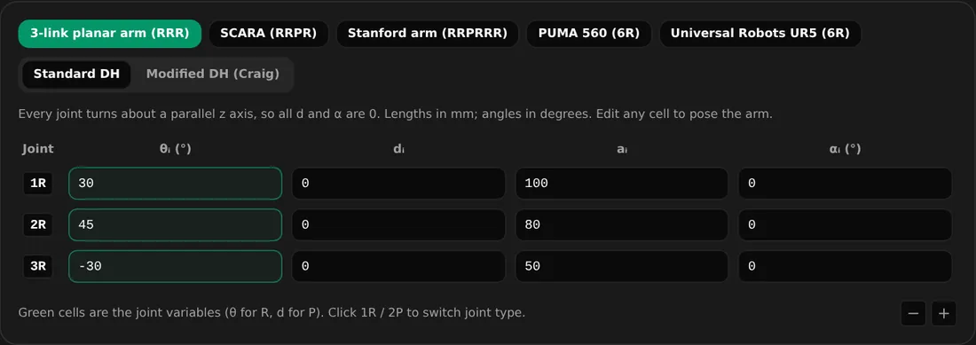
The DH table. The green cells are the joint variables, θ for a revolute joint.
With d = 0 and α = 0, each Aᵢ reduces to a rotation by θᵢ plus a step of aᵢ along the rotated x axis. Here they are, the general form first:
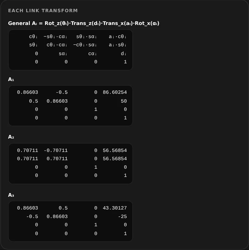
Each link matrix. A₁'s last column is (100 cos 30°, 100 sin 30°) = (86.60, 50): link 1's tip in frame 0.
Multiplying A₁ · A₂ · A₃ gives the end effector:
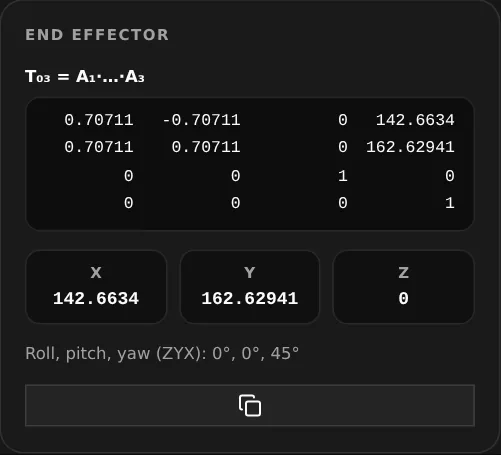
T₀³: the tool is at x = 142.66 mm, y = 162.63 mm, turned 45° (30° + 45° − 30°).
Check it by hand. For a planar arm the position must equal x = L₁cos θ₁ + L₂cos(θ₁+θ₂) + L₃cos(θ₁+θ₂+θ₃) = 100 cos 30° + 80 cos 75° + 50 cos 45° = 86.60 + 20.71 + 35.36 = 142.66, and the same with sines for y = 50 + 77.27 + 35.36 = 162.63. When the DH answer and the planar formula agree, the table is right. This is the fastest sanity check there is.
A real robot: the PUMA 560
The PUMA 560 is the classic six-axis arm in robotics courses. Its joint axes alternate between parallel and perpendicular, which is where the ±90° twists come from:
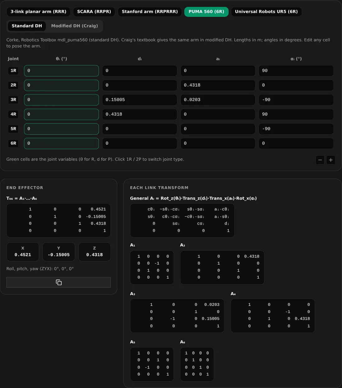
The PUMA 560 at its zero pose: the tool sits at (0.4521, −0.15005, 0.4318) m with no rotation, the same answer as Corke's Robotics Toolbox.
Two details are worth noticing. The x position, 0.4521 m, is simply a₂ + a₃ = 0.4318 + 0.0203: at zero, the upper arm and the forearm offset both point along x. And the twists cancel in pairs (+90, −90, +90, −90), so at zero the tool frame ends up aligned with the base frame.
Standard or modified DH?
Craig's Introduction to Robotics uses modified DH, where frame i sits at the near end of link i and each row holds αᵢ₋₁ and aᵢ₋₁ from the previous link: Aᵢ = Rot_x(αᵢ₋₁) · Trans_x(aᵢ₋₁) · Rot_z(θᵢ) · Trans_z(dᵢ). The same robot gets a different table, so before comparing numbers, check which convention your textbook, your lecturer or your robot's datasheet uses. The calculator switches between the two.
Common mistakes
- Mixing conventions: a standard-DH table evaluated with the modified formula, or the reverse.
- Degrees and radians: a calculator in radian mode turns 90 into 90 radians.
- Multiplying in the wrong order. Matrix multiplication is not commutative: T = A₁A₂A₃, not A₃A₂A₁.
- Signs of a and α. The UR5's a₂ and a₃ are negative in Universal Robots' own table. That is not a typo.
- Forgetting the tool. The last frame is at the wrist; a gripper adds one more fixed transform.
Try it yourself
Enter your own table, or start from the 3-link arm, SCARA, Stanford arm, PUMA 560 or UR5 presets, in the DH parameters calculator. It shows every Aᵢ in symbols and numbers, T₀ⁿ and the roll-pitch-yaw angles. For a two-link planar arm, the forward and inverse kinematics tools draw the arm, and the joint torque calculator sizes the motors to hold it.
For a related walkthrough, read Steps per mm: How to Calculate and Calibrate.