A circuit that worked on a breadboard often stops working the moment it moves to perfboard. The parts are the same; what changed is that every connection is now a solder joint you placed by hand, and one wire in the wrong hole is enough. The fix is cheap: plan the layout on paper or on screen first, check it, then solder. This guide walks through that planning the way it is done on real boards.
Perfboard, stripboard or breadboard?
Breadboard is for trying ideas: nothing is permanent, but contacts are loose and long jumper wires pick up noise. Perfboard (perforated board) has an isolated copper pad on every hole, so you make every connection yourself with wire or solder bridges. It is flexible and suits compact or irregular circuits. Stripboard, often sold as Veroboard, has long copper strips joining whole rows of holes. Fewer wires are needed, because parts on the same strip are already connected, but you have to cut the strip wherever a connection must stop, especially between the two rows of pins under a chip.
A rough rule: stripboard is faster for circuits with an IC and a handful of parts; perfboard is better when the circuit is dense, oddly shaped, or carries more current than thin strips like.
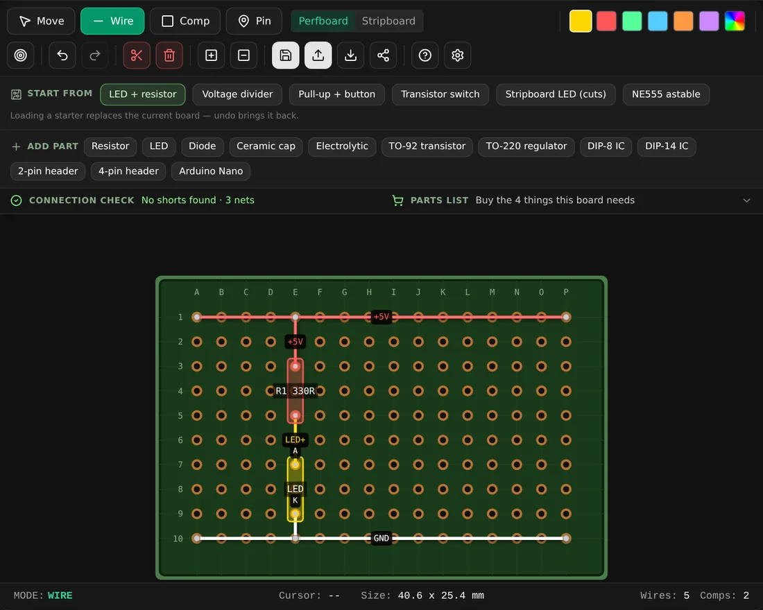
Perfboard: every pad is separate, so each connection is a wire you add. Here a resistor and an LED in series between a +5V rail and ground.
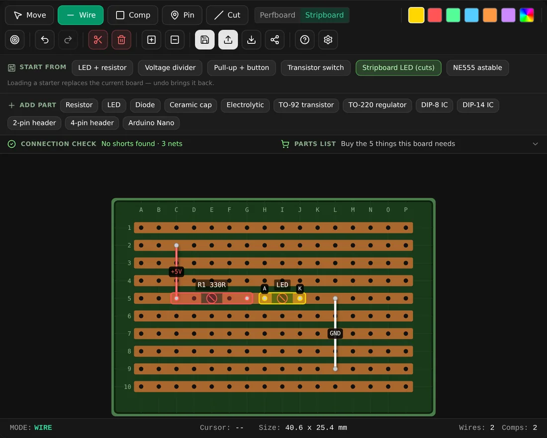
Stripboard: the copper strips do most of the wiring. Because the resistor and LED lie along one strip, a track cut (⊘) between each part's legs is what keeps them from being shorted out.
Step 1: Start from a clean schematic
Draw or print the schematic and number every net (every set of points that must be joined): +5V, GND, OUT, and so on. A layout is just the job of making each net real on the board, so you need to know what they are. Work out component values first: an LED resistor, a voltage divider or a 555 timer's timing parts. Layout tools check connections, not values.
Step 2: Place the big parts first
Put the integrated circuits, connectors and anything mechanical (pots, switches, screw terminals) down first, because they are the hardest to move later.
- Leave two or three rows free on each side of a chip for the parts and wires that connect to its pins.
- Put connectors on the edges of the board, where cables will actually reach them.
- Keep power entry and its decoupling capacitor next to the chip: a 100 nF capacitor across VCC and GND, as close to the pins as possible.
- On stripboard, lay chips across the strips, so each pin lands on its own strip, then cut every strip between the two rows of pins.
Step 3: Add the small parts along the signal path
Follow the schematic from input to output and place resistors, capacitors and transistors in that order, close to the pins they connect to. Short connections are both easier to solder and less noisy. On stripboard, a part should bridge two strips, or lie along one strip with a cut between its legs: a resistor whose two legs sit on the same uncut strip is shorted out.
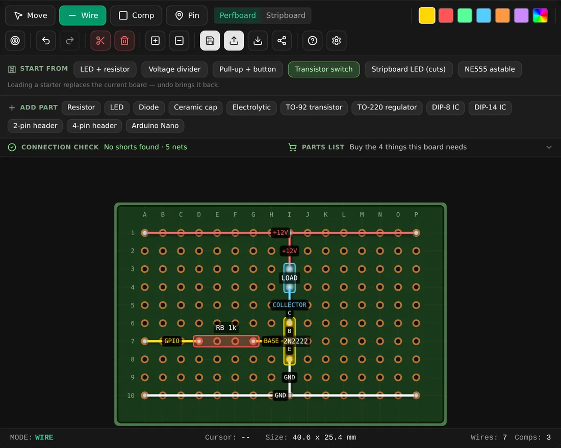
A transistor switch laid out along its signal path: GPIO input, base resistor, transistor, then the load. Each part sits next to the pin it connects to, so no wire crosses another. The transistor switch guide works out its base resistor.
Step 4: Route power and ground as rails
Give +V and ground their own long runs, ideally along the top and bottom edges, the way a breadboard does. Every part then reaches power with a short wire, and you can see at a glance that nothing is missing a ground. Use thicker wire for anything carrying more than a few hundred milliamps.
Step 5: Route the remaining wires
Now join what is left. Keep wires short and straight, avoid crossing over the top of parts you might need to replace, and use colours consistently: red for positive supply, black for ground, another colour for signals. On stripboard you will need far fewer wires; most "wires" are the strips themselves.
Step 6: Check every net before soldering
This is the step that saves hours. Go net by net and confirm that everything that should be joined is joined, and that nothing else is. On stripboard, check that every cut is where it should be, because a missing cut is the single most common stripboard fault. A perfboard and stripboard simulator does this check live: it shows which holes are electrically connected, flags parts whose legs are shorted by a strip, and warns when the supply rails touch.
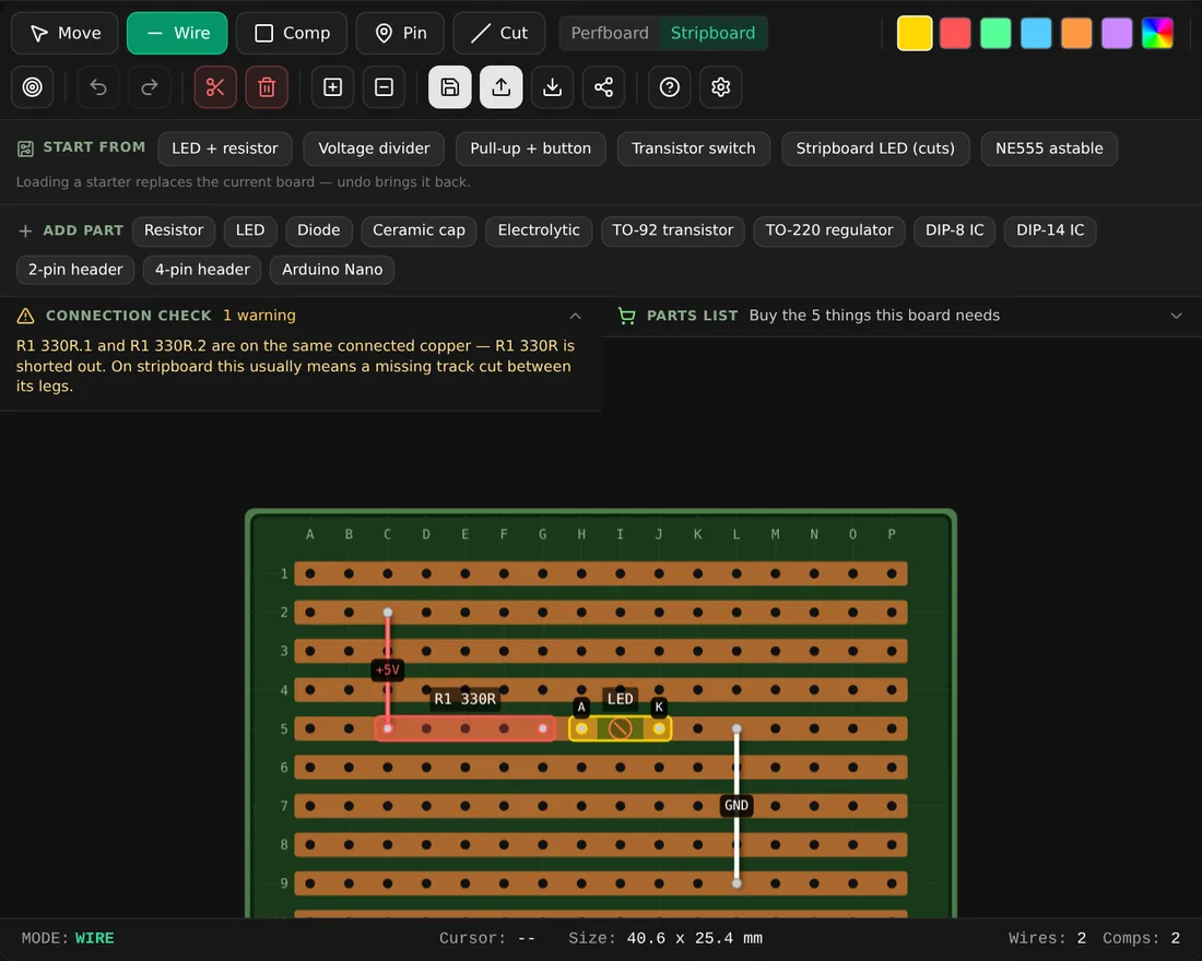
The same stripboard board with one cut forgotten. The connection check catches it before you solder: "R1 330R is shorted out. On stripboard this usually means a missing track cut between its legs."
Step 7: Solder in the same order
Solder low parts first (wire links, resistors, diodes), then IC sockets, then taller parts, so the board lies flat while you work. Use a socket for every chip; it protects the chip from heat and makes it replaceable. After each group, check again with a continuity tester before moving on.
A worked example: the 555 astable
The classic NE555 square-wave oscillator is a good first board. The 8-pin chip goes in the middle. Pins 2 and 6 join together (trigger and threshold), pin 4 (reset) goes to VCC, and pin 7 (discharge) sits between the two timing resistors RA and RB. The timing capacitor runs from pins 2 and 6 to ground, a 10 nF capacitor decouples pin 5, and the output comes from pin 3. The frequency is f = 1.44 / ((RA + 2·RB)·C).
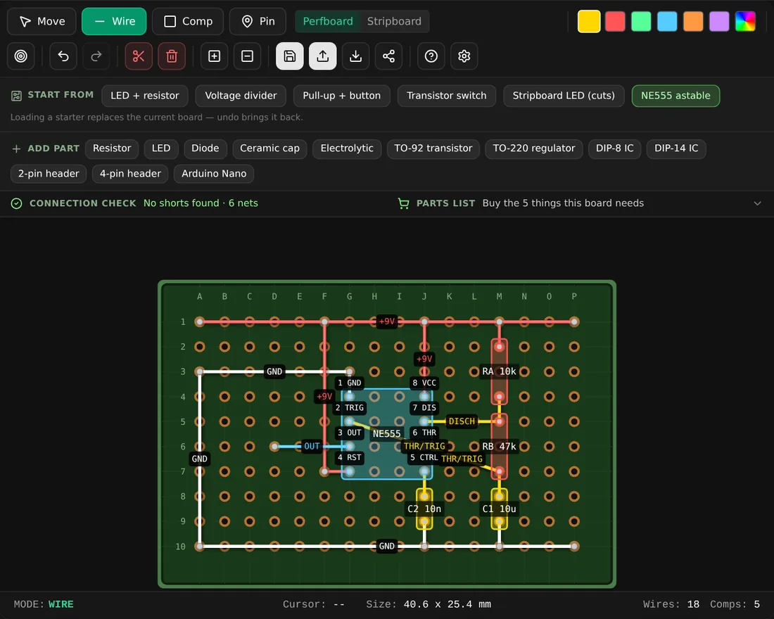
The 555 astable as the simulator lays it out: power along the top, ground along the bottom, the chip in the middle with its timing parts beside the pins they serve. 11 nets, no shorts.
With the values on that board, RA = 10 kΩ, RB = 47 kΩ and C = 10 µF, the frequency is 1.44 / ((10 k + 2 × 47 k) × 10 µF) = 1.44 / 1.04 ≈ 1.4 Hz, about one and a half flashes a second for an LED on the output, and the output is high for (RA + RB) / (RA + 2·RB) = 57 / 104 ≈ 55 % of each cycle. The 555 timer calculator does this sum for any values.
On stripboard, place the chip across the strips and cut the four strips between its pin rows. Put RA and RB on adjacent strips beside pins 7 and 6, and the capacitor next to pin 2. The simulator has this circuit as a ready-made example: load "NE555 astable", move parts around and watch the connection check update.
Common mistakes
- No cut under the chip on stripboard, so opposite pins are shorted.
- A part lying along one strip, so it does nothing.
- Missing decoupling capacitor, which shows up as a circuit that works on the bench and misbehaves near a motor.
- Connectors in the middle of the board, where cables pull on the joints.
- Planning in your head: the layout looked obvious until the third wire.
The short version
Number the nets, place big parts and connectors first, follow the signal with the small parts, give power and ground their own rails, check every net and cut, then solder from low to tall. Ten minutes of planning on screen is the difference between a board that works first time and an evening with a desoldering pump. Try it on your next circuit in the perfboard simulator, then share the link with whoever is helping you debug it.
For finished examples, see the perfboard layout library: checked layouts for a 7805 supply, a 555 timer, an Arduino Nano project and more.