A microcontroller pin gives 3.3 V or 5 V and a few milliamps. A 12 V LED strip, a buzzer or a relay coil wants more voltage, more current, or both. The standard fix is one NPN transistor as a low-side switch: the load sits between +12 V and the transistor's collector, the emitter goes to ground, and the pin drives the base through a resistor. When the pin goes high, the transistor turns fully on and the load runs from 12 V; when it goes low, the transistor turns off.
The only part that needs working out is the base resistor. This guide works it out for a real part, the 2N2222, then lays the circuit out on perfboard. The part figures come from onsemi's P2N2222A datasheet, and every result was computed with tested code in this site's electronics library, not by hand.
The circuit
| Part | Job |
|---|---|
| Q1, 2N2222 NPN in TO-92 | The switch |
| RB, base resistor | Limits the current out of the logic pin into the base |
| The load | Anything resistive that runs from 12 V: an LED strip section, a lamp, a buzzer |
| Flyback diode (only for coils) | Needed for relays, motors and solenoids, see below |
The datasheet limits that matter here: 40 V between collector and emitter when off, 600 mA continuous collector current, and 625 mW of heat in free air at 25 °C. A 12 V load is comfortably inside the voltage limit.
The two grounds must be joined. The base current flows out of the pin, through the base and emitter, and back to the microcontroller's ground. If the microcontroller's ground isn't connected to the 12 V supply's ground, there's no path back and the transistor never turns on. This is the most common reason a transistor switch "does nothing".
Why "saturated", and why not just use hFE
A transistor used as a switch should be fully on (saturated), so the voltage across it is as small as possible and it barely warms up. In saturation the collector-emitter voltage, VCE(sat), is at most 0.3 V for the 2N2222 at 150 mA, according to its datasheet.
The tempting calculation divides the load current by the gain, hFE. The datasheet says hFE is at least 100 at 150 mA, so a 100 mA load would seem to need just 1 mA of base current. But that gain figure is measured with 10 V across the transistor, which is the opposite of saturated. At 1 V across it the minimum gain drops to 50, and saturation needs the voltage lower still. Size the base resistor from hFE = 100 and the transistor only half switches on: it drops volts, gets hot, and the load runs dim.
The rule that works is a forced beta of 10: give the base a tenth of the collector current. It's the same ratio the datasheet uses for its own saturation figures (150 mA with 15 mA into the base, 500 mA with 50 mA), so the 0.3 V figure holds.
So the base resistor is:
IB = IC / 10
RB = (V_pin − VBE) / IB        with VBE ≈ 0.7 V
Then pick the nearest standard resistor below that value, so the base gets at least that much current.
Worked example 1: the simulator's starter circuit
The perfboard simulator's "Transistor switch" starter drives the base from a 3.3 V pin through 1 kΩ:
- Base current: (3.3 − 0.7) V / 1,000 Ω = 2.6 mA
- At a forced beta of 10 that saturates loads up to 26 mA
So the starter as drawn is right for a small load: an indicator lamp or a short run of LEDs drawing 20 mA. The transistor then dissipates 0.3 V × 20 mA + 0.7 V × 2.6 mA = 7.8 mW, nothing at all for a part rated at 625 mW.
Worked example 2: a 100 mA load
Now a load of 120 Ω on 12 V, such as a section of LED strip. With 0.3 V across the transistor, the load current is (12 − 0.3) / 120 = 97.5 mA.
From a 3.3 V pin:
- IB = 97.5 mA / 10 = 9.75 mA
- RB = (3.3 − 0.7) / 0.00975 = 266.7 Ω, so the next standard value down is 220 Ω
- With 220 Ω, the base gets 11.8 mA, enough to saturate up to 118 mA
- Heat in the transistor: 37.5 mW
From a 5 V pin (an Arduino Uno or Nano):
- RB = (5 − 0.7) / 0.00975 = 441 Ω, so the next standard value down is 390 Ω
- The base gets 11.0 mA, enough to saturate up to 110 mA
- Heat in the transistor: 37.0 mW
Keep the 1 kΩ from the starter with this load and the base gets only 2.6 mA, enough to saturate 26 mA, not 97.5. The transistor would sit half on.
Around 10 to 12 mA is also about as much as you should ask of a logic pin; check your microcontroller's datasheet for its per-pin limit. At 500 mA a forced beta of 10 would need nearly 49 mA of base current, which no logic pin can supply, and the datasheet allows up to 1.0 V across the transistor at that current. For loads past about 100 to 150 mA, use a logic-level MOSFET instead: its gate takes almost no steady current. The H-bridge MOSFET loss guide shows how to check a MOSFET's heat.
The layout on perfboard
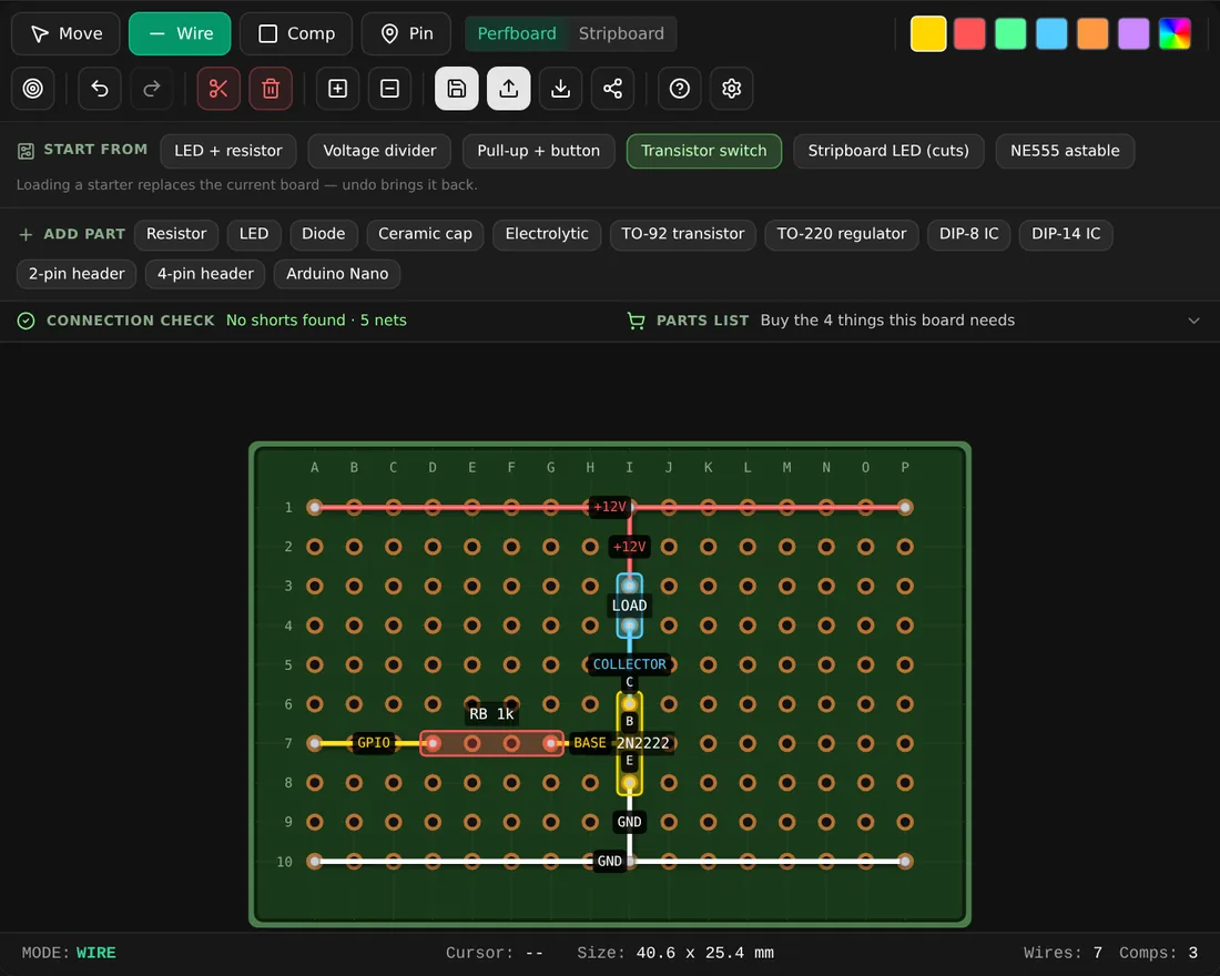
The starter as the simulator lays it out. Open the perfboard simulator and press Transistor switch to load it.
The board is 16 columns (A to P) by 10 rows:
- Rails first. +12 V along row 1, ground along row 10. Every connection to power is then a short drop.
- Transistor in the middle of a column. The 2N2222 sits in I6, I7, I8 as collector, base, emitter. For the onsemi P2N2222A, pins 1, 2 and 3 really are collector, base and emitter, but other 2222-type parts in TO-92 can be wired in a different order, so check the datasheet of the part in your hand before soldering.
- Load above it, on the same column. The load connects at I3 and I4: a wire from the +12 V rail at I1 to I3, and from I4 down to the collector at I6. The current path is then one straight line down column I.
- Base resistor across from the pin. RB runs from D7 to G7, the GPIO wire comes in from A7, and a short wire G7 to I7 reaches the base.
- Emitter straight to ground. A wire from I8 down to the ground rail at I10.
The connection check should say No shorts found · 5 nets: +12V (with the load's top), COLLECTOR (the load's bottom and Q1's collector), BASE (RB and Q1's base), GPIO, and GND (with Q1's emitter). If it reports a label split across pieces that aren't joined, a wire is stopping one hole short of the rail.
When you change the load, change RB to match: 220 Ω or 390 Ω for the 100 mA example above. Use the resistor colour code decoder to check the part before it goes in.
Relays, motors and solenoids: add a flyback diode
A coil stores energy in its magnetic field. When the transistor switches off, that energy has to go somewhere, and the coil drives the collector far above 12 V in an instant, well past the 2N2222's 40 V limit. One diode fixes it: put it across the coil, reverse biased, with its stripe (cathode) to +12 V and the other end to the collector. When the transistor turns off, the coil current circulates through the diode and dies away harmlessly. A 1N4001 to 1N4007 is the usual choice for relays and small motors.
A resistive load such as an LED strip doesn't need the diode, which is why the starter doesn't have one. On the board, the diode goes beside the load, across I3 and I4's two ends.
One more part worth adding: a base pull-down
While a microcontroller boots, its pins float, and a floating base can turn the transistor partly on. A 10 kΩ resistor from base to emitter holds it firmly off until the pin takes over. It also takes a little of the base current, so if you add it, check that the base current left over still saturates the load.
Check before you power up
- Grounds joined: the microcontroller's GND to the 12 V supply's GND.
- Transistor pins checked against the datasheet of the part you actually have.
- RB matches the load: about 1 kΩ up to 26 mA from 3.3 V, 220 Ω for about 100 mA.
- A diode across any coil, stripe to +12 V.
- The simulator's connection check shows no shorts and no split labels.
Plan the rest of the board with the perfboard layout guide, and if the load is an LED with its own resistor, size that with the LED resistor calculator.